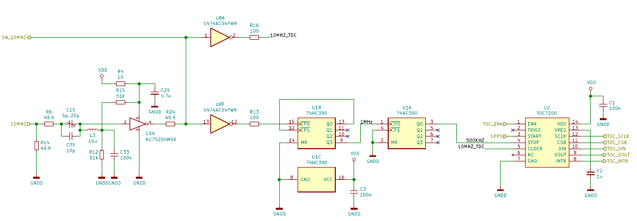
One of the main building blocks of the Rb-GPSDO is the part that measures the offset between the timing signal from the GPS and the LO. In this design, the measurements are done with a TDC7200 Time-to-Digital Converter by Texas Instruments. The following graphic is the TIC part of the whole circuit.
The 1PPS timing signal from the GPS is directly provided to the START input of the TDC7200 (U2).
The 10MHz signal from the LO is first fed into a sine-to-square block. An inverter (U8F) feeds the resulting square wave into a divide-by-20 stage formed by a 74HC390 decade counter. The output is a 500kHz signal which is connected to the STOP input of U2.
The TDC7200 needs a reference clock to calibrate its internal high-frequency ring oscillator. Since absolute measurement accuracy is not required for this GPSDO, conveniently the LO can also supply the reference clock. Another inverter stage (U8A) supplies the squared-up LO signal to the reference clock input of U2.
With this setup, each pulse of the 1PPS timing reference starts a measurement and the next rising edge of the 500kHz signal, which has a fixed phase relation to the LO output, stops the measurement. The time between START and STOP is a measure for the phase offset between the timing signal and the LO. The LO frequency is locked to the timing reference if the phase offset stays constant.
However, keeping the phase offset constant is quite difficult because of the uncertainty of the measurement and numerical issues when calculating the differences between consecutive measurements. For example, if the measurement uncertainty is 100ps, the frequency can drift 100ps/s without it showing up in the measurements. Due to the averaging necessary to eliminate the 1PPS noise (over thousands of seconds), errors will accumulate quickly as you keep adding measurements, each of them adding another 100ps/s of uncertainty.
Therefore, the most reliable way to lock the frequency of the LO is to lock its phase to the timing reference. Here, each measurement is independent of the previous, as it is referenced to a fixed phase difference. The necessity to average out 1PPS noise is still the same, but the measurement uncertainty does not add up.
It is advisable to supplement the TIC shown above with a counter for timestamping the 1PPS pulses from the GPS. The circuit as implemented has a capture range of 2 microseconds. If the phase ever drifts more than this, for example when there is no GPS coverage, the measured time interval will wrap. However, for the purpose of creating a frequency standard this is of no consequence.
For the last couple of months I have worked on a number of small projects, including the repair of a Rubidium frequency standard that I bought cheaply off of Ebay. But while these frequency standards have exceptional stability and aging characteristics, they still need to be calibrated from time to time.
For that purpose, I bought a 10-digit frequency counter, a Racal 1998. I also obtained a number of GPSDOs. GPSDO is short for "GPS Disciplined Oscillator". You can buy them for less then €100 as they are commonplace telecom equipment and found as frequency and time references in cellular network base stations. Network operators replace them routinely and the scrap can be found on the usual online marketplaces.
A GPSDO consists of a local oscillator of good quality and a GPS receiver. Most of the time the LO is an OCXO, an Oven Controlled Crystal Oscillator. As the name suggests, an OCXO is a crystal oscillator where the crystal is heated to a stable temperature well above room temperature (50°C to 60°C is not uncommon). This heating foregoes crystal aging and reduces the frequency drift to a few PPB over time. It also reduces the influence of environmental temperature changes, which would otherwise affect the stability of the oscillator output.
The GPS receiver provides a timing reference, typically in form of a 1PPS (one-pulse-per-second) signal that has exceptional long-term stability. The timing signal is used to compensate the remaining aging of the LO. A GPSDO combines the short-term stability of a crystal oscillator with the long-term stability of an exact timing reference.
The concept of the GPSDO got me interested and I started wondering how it could work. The trivial approach is, as the timing pulses arrive in constant intervals, it should be easy to just count the cycles of the LO between two pulses and adjust its frequency according to the result. However, the frequency of the LO is usually 10MHz, i.e. 100ns cycle time. That would result in a frequency accuracy of only +/- 100ns/s, or 100ppb. For a 10MHz frequency, that computes to +/- 1Hz of deviation. Definitely not very accurate, and the output would wander between the two extremes constantly, so it wouldn't be very stable, either. Another appruach is needed.
Over on the EEVBlog forum I found a number of DIY GPSDO projects and one of them intrigued me through its simplicity and performance. Conceptually, it is similar to a number of other DIY projects: Instead of implementing a frequency counter, a PLL compares the phase offset between the time signal pulse and a selected edge of the LO output. This phase offset is then eliminated by the PLL regulation.
A very simple implementation of this design is the GPSDO by James Miller, G3RUH (link). The output of an XOR phase discriminator is low-pass filtered, buffered and directly applied to the control input of an OCXO.
Another design variant feeds the output of the phase discriminator into the ADC of an Arduino (or similar) micro controller, which then implements a PLL in software to lock the LO to the GPS timing signal. These designs achieve a measurement resolution in the single nanosecond range. Averaging the measurements over a longer time period (hundreds of seconds) achieves the necessary stability. The most simple implementation of this design is Lars Walenius' DIY GPSDO, which was discussed on the EEVBlog forum in great detail.
The design I came up with, with the help of other forum members, follows the same principle but uses an integrated Time-To-Digital converter instead of an analog interpolator. This avoids some of the problems with temperature drift and selection of suitable components that complicate reproducibility of Lars Walenius' design.
The heart of the design is the TDC7200 by Texas Instruments. Its original use case are ultrasonic flow meters but at its guts it's just a stopwatch. It measures the time between a start and a stop signal presented to its inputs. With a resolution of around 55 picoseconds it's much more sensitive than needed. It's cheap, requires only few external components and can be controlled through a SPI interface.
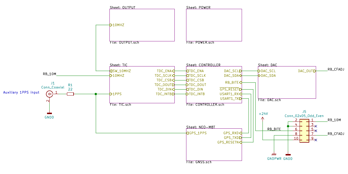
The following graphic shows a high-level outline of the GPSDO.
GPSDO High-Level Design
The timing signal from the GPS receiver (1PPS) is fed into a Time Interval Counter (TIC) together with a 10MHz reference signal from the LO. In my case, the LO is a Datum LPRO-101 Rubidium frequency standard. A small micro controller, an STM32F042, acts as the central intelligence of the system. It reads the measured time interval between the GPS 1PPS signal and a selected edge of the LO signal and computes a correction factor to be applied to the LO frequency. A DAC converts the correction factor to an analog voltage which is then applied to the adjustment input of the LO.
The controller also connects to the GPS receiver to allow configuration of the time pulse, start a self-survey, provide a known location or simply query status of visible and tracked satellites.
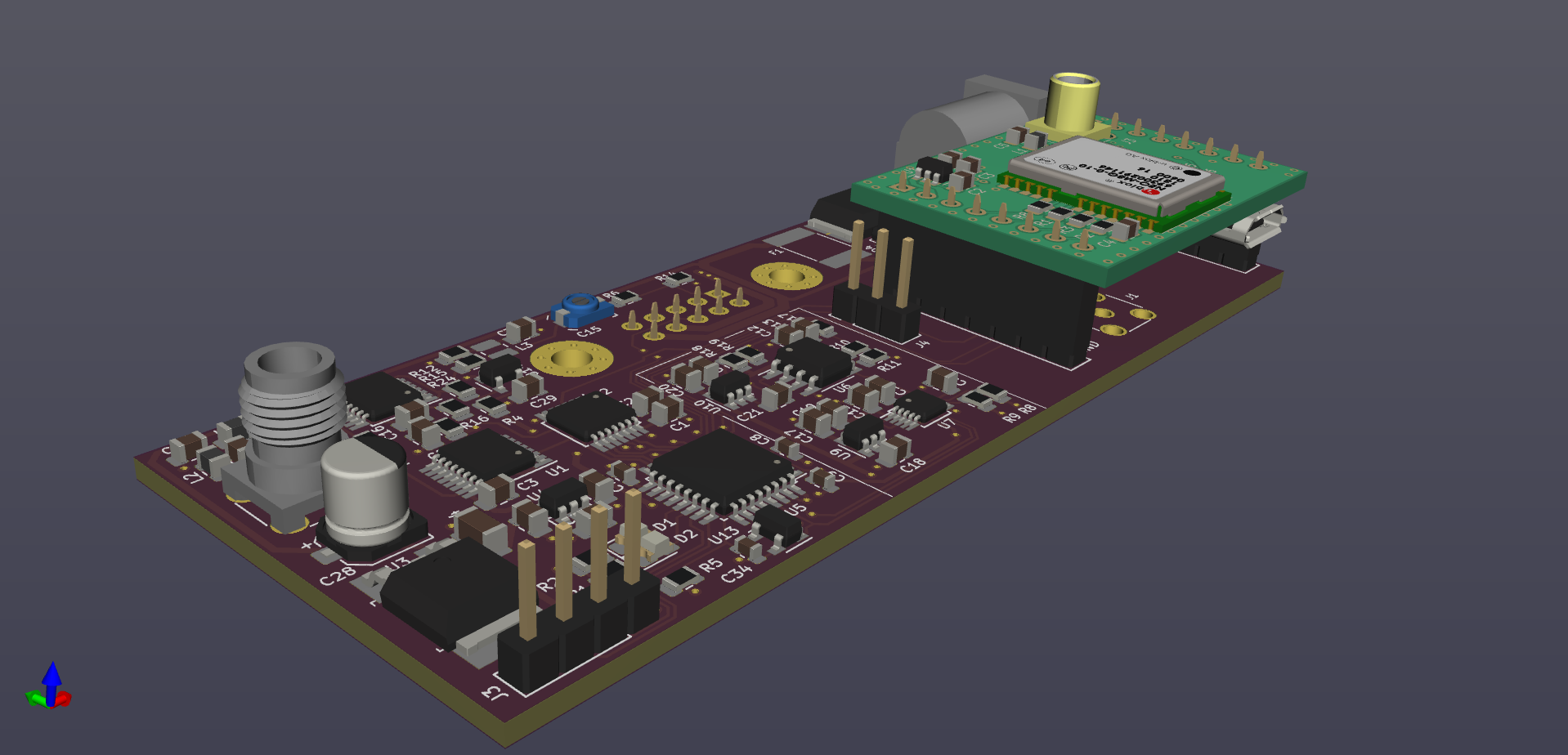
The GPS receiver itself is a Ublox NEO-M8T timing receiver that can work in "overdetermined clock" mode to achieve better precision of the time pulse signal. I bought two modules on Ebay for about 25€ each and designed a small breakout PCB that can be plugged onto the main GPSDO PCB.
3D rendering of the GPSDO
The project is more or less complete now and I'm working on a few minor improvements, but the design itself has been verified and it works very well.