One of the main building blocks of the Rb-GPSDO is the part that measures the offset between the timing signal from the GPS and the LO. In this design, the measurements are done with a TDC7200 Time-to-Digital Converter by Texas Instruments. The following graphic is the TIC part of the whole circuit.
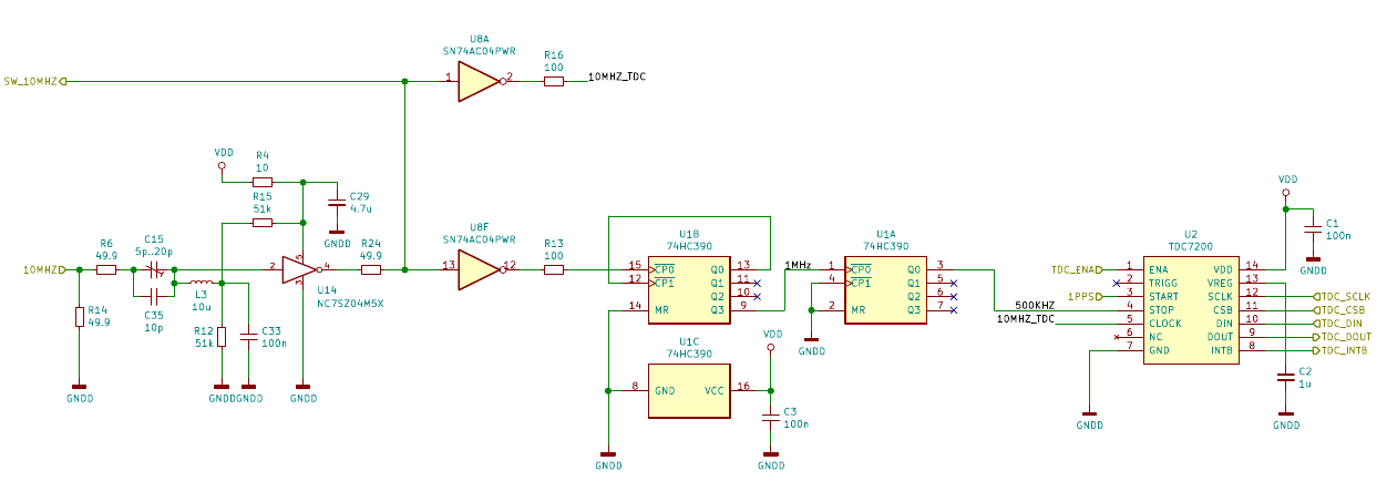
The 1PPS timing signal from the GPS is directly provided to the START input of the TDC7200 (U2).
The 10MHz signal from the LO is first fed into a sine-to-square block. An inverter (U8F) feeds the resulting square wave into a divide-by-20 stage formed by a 74HC390 decade counter. The output is a 500kHz signal which is connected to the STOP input of U2.
The TDC7200 needs a reference clock to calibrate its internal high-frequency ring oscillator. Since absolute measurement accuracy is not required for this GPSDO, conveniently the LO can also supply the reference clock. Another inverter stage (U8A) supplies the squared-up LO signal to the reference clock input of U2.
With this setup, each pulse of the 1PPS timing reference starts a measurement and the next rising edge of the 500kHz signal, which has a fixed phase relation to the LO output, stops the measurement. The time between START and STOP is a measure for the phase offset between the timing signal and the LO. The LO frequency is locked to the timing reference if the phase offset stays constant.
However, keeping the phase offset constant is quite difficult because of the uncertainty of the measurement and numerical issues when calculating the differences between consecutive measurements. For example, if the measurement uncertainty is 100ps, the frequency can drift 100ps/s without it showing up in the measurements. Due to the averaging necessary to eliminate the 1PPS noise (over thousands of seconds), errors will accumulate quickly as you keep adding measurements, each of them adding another 100ps/s of uncertainty.
Therefore, the most reliable way to lock the frequency of the LO is to lock its phase to the timing reference. Here, each measurement is independent of the previous, as it is referenced to a fixed phase difference. The necessity to average out 1PPS noise is still the same, but the measurement uncertainty does not add up.
It is advisable to supplement the TIC shown above with a counter for timestamping the 1PPS pulses from the GPS. The circuit as implemented has a capture range of 2 microseconds. If the phase ever drifts more than this, for example when there is no GPS coverage, the measured time interval will wrap. However, for the purpose of creating a frequency standard this is of no consequence.
Is the voltage divider R15/R12 giving you the desired offset?
U14 has a high input level of 0,7V and a low input level of 0,3V, so i think the offset should be between this levels to get a symetrical square wave.
I think a divider of 120k fixed + 100k adjustabel and 33k to ground should give you a possibility for adjustments.
Greetings Lena
Lena, thanks for the suggestion. You're right, the NC7SZ04M5X is probably not optimally biased in this circuit. It seems, though, that the tank circuit with C15||C35 and L3 when tuned to resonance gives a large enough signal at the input so that it doesn't matter. I get close to 50% duty cycle. Still, correcting the bias or using e.g. an SN74LVC1G04 could improve the performance. The SN74LVC1G04 has a larger "forbidden zone" between high and low so that I could go without a trimpot (there's no space left on the PCB).